
Choosing electrical controls affects how safely, reliably, and efficiently a machine operates. A control panel may look simple, yet a mismatched component can cause nuisance trips, slow response, or difficult maintenance. Start with the actual load, supply voltage, operating environment, and required functions. A motor near a washdown line, for example, needs different protection from a small fan in a clean cabinet. Details matter.
The most advanced device is not always the right choice. Consider contactors, relays, drives, sensors, and protective devices as parts of one system, not isolated purchases. Check ratings against equipment data, expected starting current, switching frequency, and ambient temperature. Then assess enclosure space, wiring access, diagnostics, and replacement availability. A neat drawing helps. But field conditions can still surprise you; cable routes, heat, and dust often differ from early assumptions.
This guide explains how to compare electrical controls using practical criteria, from application requirements and compatibility to safety features, lifecycle costs, and support. It also highlights questions to ask suppliers and installers before finalizing a design. No checklist replaces a qualified review of the complete system. That may sound cautious, because it is. Choosing well means balancing performance with serviceability, documenting decisions, and revisiting assumptions when operating data becomes available. Good controls should make a machine predictable, not merely impressive on a specification sheet.
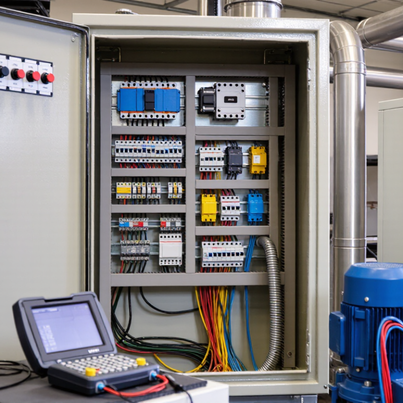
Defining electrical control requirements begins with the machine, not the panel drawing. List each load’s rated voltage, phase, current, starting method, duty cycle, and expected operating hours.
The U.S. Department of Energy’s 2014 sourcebook, Improving Motor and Drive System Performance, reports a striking figure: motor-driven systems use about 54% of U.S. manufacturing electricity. That makes operating profile a design input, not a footnote. Small details matter.
Translate production needs into control functions: start/stop logic, speed ranges, interlocks, alarms, and safe responses to sensor failure. Record available fault current, ambient temperature, vibration, and exposure to dust or washdown before selecting components. Specify what must happen after a power loss, communications fault, or emergency stop; vague wording can cause costly commissioning debates. Have a qualified electrical professional review protection, wiring, and safety functions against applicable standards.
Document expected I/O, network interfaces, operator permissions, and room for future sensors. Ask operators and maintenance staff to walk through real tasks, including clearing jams and restarting after faults. Set acceptance checks for response time, alarm behavior, and motor direction before installation. One assumption often needs revisiting: a line’s “normal” load may change after process upgrades. Record measured values and unresolved questions in the specification instead of hiding them behind “to be confirmed.”
Choosing electrical controls starts with the load’s real behavior, not just its nameplate. Check operating voltage, continuous current, and starting current, especially for motors that draw a brief surge. A control rated only for steady operation may wear quickly under frequent starts. Note how often the equipment switches and whether loads run together. Heat adds up.
Next, consider operating conditions. Repeated cycling, vibration, and long shifts can affect component life. A control cabinet beside a hot process may need more attention to temperature than one in a cool room. Dust, moisture, and cleaning practices also matter. Match the enclosure protection to the actual exposure, rather than guessing from the room’s appearance. A dry workshop can still have fine dust near cutting equipment.
The surrounding environment should shape installation and maintenance choices. Allow space for airflow, keep wiring clear of moving parts, and check whether technicians can safely inspect terminals. In practice, assumptions about future load changes are easy to miss. Review likely additions, such as a larger motor or longer operating hours, before selecting ratings. If conditions are uncertain, document what is known and verify measurements on site. That detail matters. A careful reassessment may take time, but replacing controls after repeated trips or overheating can take longer.
Electrical controls should match the load, operating pattern, and level of adjustment required. A contactor is a practical choice for simple on/off duty, such as switching a fixed-speed pump. A soft starter reduces the jolt of motor startup, which can ease stress on belts and pipes. For frequent speed changes, a variable-frequency drive (VFD) can adjust motor speed to demand. A programmable logic controller (PLC) coordinates sequences, sensors, and interlocks across a machine or process. These devices solve different problems; treating them as interchangeable can add cost without improving performance.
The U.S. Department of Energy’s 2014 Improving Motor and Drive System Performance sourcebook estimates that motor-driven systems account for about 69% of electricity use in U.S. industry. That makes control selection worth examining, especially for pumps and fans that run for long periods. A VFD may reduce energy use when a process can operate below full speed, but it is not automatically the best choice for every motor. Check the motor’s operating range, load profile, environment, and compatibility before specifying one. Real operating data matters. In practice, that data may be incomplete, so assumptions should be revisited after installation.
Tips: Record motor current and run time before choosing a control. Compare expected savings with installation and maintenance needs, and confirm the control suits the actual load. A quick site check can reveal surprises.
How to Choose the Right Electrical Controls?
Verify Compatibility, Safety, and Compliance
Begin with the equipment’s actual operating conditions, not just its catalog description. Match supply and control voltages, phase, current, load type, and switching frequency. Check that the control’s short-circuit current rating meets or exceeds the available fault current at its installation point. Confirm enclosure protection and temperature limits suit the location; dust, moisture, and heat can undermine an otherwise correct selection. Small details matter.
Safety depends on the full installation. Verify overcurrent protection, disconnecting means, grounding, and coordination between components. OSHA’s 29 CFR 1910.303 requires listed or labeled equipment to be installed and used according to its instructions. The U.S. Bureau of Labor Statistics’ 2022 Census of Fatal Occupational Injuries recorded 145 fatal work injuries involving exposure to electricity. That figure is a practical reminder: a control’s rating alone cannot make a system safe.
Check applicable electrical codes and product standards for the machine’s location and use. Review the manufacturer’s wiring diagrams, terminal limits, and installation instructions before energizing the panel. A mismatch between a motor’s starting current and a controller’s rating may appear only under load. Still, checklists are imperfect. Record the ratings, inspection results, and any unresolved assumptions, then have a qualified person verify the completed installation.
| Selection dimension | What to verify | Practical decision check | Evidence to review |
|---|---|---|---|
| Supply voltage and phase | Rated operating voltage, frequency, and number of phases for both the power circuit and control circuit. | Match the control equipment’s ratings to the actual supply. Do not assume a control coil or power supply accepts the machine’s line voltage. | Equipment nameplate, wiring diagram, and manufacturer’s electrical ratings. |
| Load type and switching duty | Load current, starting or inrush current, switching frequency, and load type, such as a motor, heater, transformer, or lighting circuit. | Select switching devices using the applicable utilization category and rated duty—not current alone. Motor starting can impose greater stress than steady-state operation. | Load data and the device’s ratings for the relevant utilization category and operating conditions. |
| Current and overload protection | Continuous current, overload requirements, conductor protection, and coordination with upstream protective devices. | Confirm that protective-device settings and ratings suit the load and installation. Motor overload protection and short-circuit protection serve different purposes. | Load calculations, protection-device data, applicable electrical code, and coordination documentation where required. |
| Short-circuit withstand rating | Available fault current at the installation point and the control assembly’s short-circuit current rating (SCCR), where applicable. | The assembly rating must be suitable for the available fault current under the applicable rules; verify any conditions or specified upstream protective devices. | Fault-current assessment, assembly markings, and documentation for the tested protective-device combination. |
| Control signals and interfaces | Control voltage, signal type, input/output ratings, communication protocol, and required isolation. | Check that sensors, controllers, relays, drives, and the control power supply use compatible signal levels and interfaces. | I/O lists, wiring diagrams, interface specifications, and device manuals. |
| Enclosure and environment | Indoor or outdoor location, dust or water exposure, corrosion, vibration, ambient temperature, and ventilation. | Choose an enclosure protection level appropriate to the installation and jurisdiction. An IP code and a NEMA enclosure type are different classification systems and are not automatically interchangeable. | Site conditions, enclosure rating, temperature limits, and installation instructions. |
| Safety functions | Required emergency-stop, guard-interlocking, safe-torque-off, or other risk-reduction functions. | Determine required safety performance through a documented risk assessment. Ordinary control components should not be assumed to provide a safety-rated function. | Risk assessment, safety-function specification, validation records, and applicable machinery-safety standards. |
| Standards and approvals | Applicable national and regional electrical, machinery, and product-safety requirements for the intended market. | Confirm the required conformity route and markings for the complete installation. Requirements vary by country, application, and equipment category. | Declarations, certification or listing records, test documentation, and applicable code or standard editions. |
| Wiring, grounding, and installation | Conductor size, terminal range, grounding and bonding, clearances, and separation of power and signal wiring. | Verify installation details against equipment instructions and local code; use qualified personnel and isolate energy before servicing. | Installation manual, approved drawings, conductor calculations, and inspection or commissioning records. |
| Maintenance and lifecycle | Expected operating cycles, replacement availability, service access, spare parts, and diagnostic needs. | Favor a design that can be safely inspected and maintained, with clear labeling and accessible documentation. | Maintenance plan, parts documentation, operating-cycle data, and as-built drawings. |
Note: Final selection and installation should be verified by a qualified electrical professional against the equipment documentation, site conditions, and requirements applicable in the installation jurisdiction.
Evaluate Installation, Maintenance, and Future Expansion
Choosing electrical controls starts with the installation site, not the catalog. Measure the panel location, door swing, cable entry points, and clearance for safe access. A unit that fits on paper may be awkward beside a pipe or in a hot, dusty room. Check supply characteristics, load requirements, enclosure rating, and project standards with a qualified electrical professional. Small details matter.
During installation, look for clear terminal markings, accessible wiring routes, and enough room to test components without disturbing neighboring circuits. Confirm that drawings match the equipment, and label both ends of field cables. This takes time. It can prevent slow fault-finding later. For maintenance, consider how technicians will reach filters, fuses, relays, and other replaceable parts. Still, tidy wiring alone does not guarantee easy servicing; technicians may need more working space than the design suggests.
Future expansion is easier to manage before the enclosure is full. Estimate likely additions, such as sensors, drives, or communication modules, then reserve suitable rail space, terminals, power capacity, and network ports. Verify that new components will work with the control architecture and protection scheme. Extra capacity has a cost, and guessing too generously can waste budget. A documented allowance is often more useful than an optimistic promise of unlimited growth.